




2026-10-23
Mandrel Bending vs. Compression Bending for Exhaust Tubing
Mandrel Bending vs. Compression Bending for Exhaust Tubing
If the bend has to stay round enough to seal at a clamp or slip joint, use mandrel bending. If the bend is a long sweep that nobody measures, compression bending usually costs less. That is the short answer.
How Mandrel Bending Works
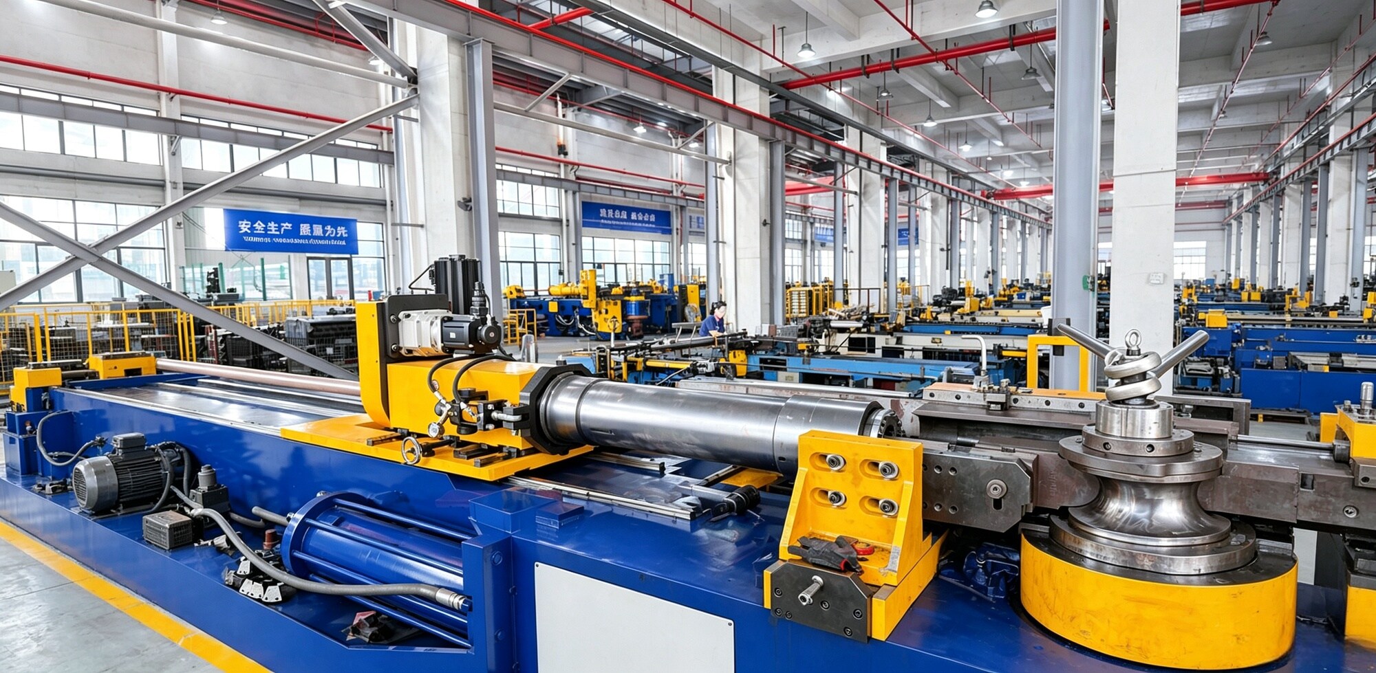
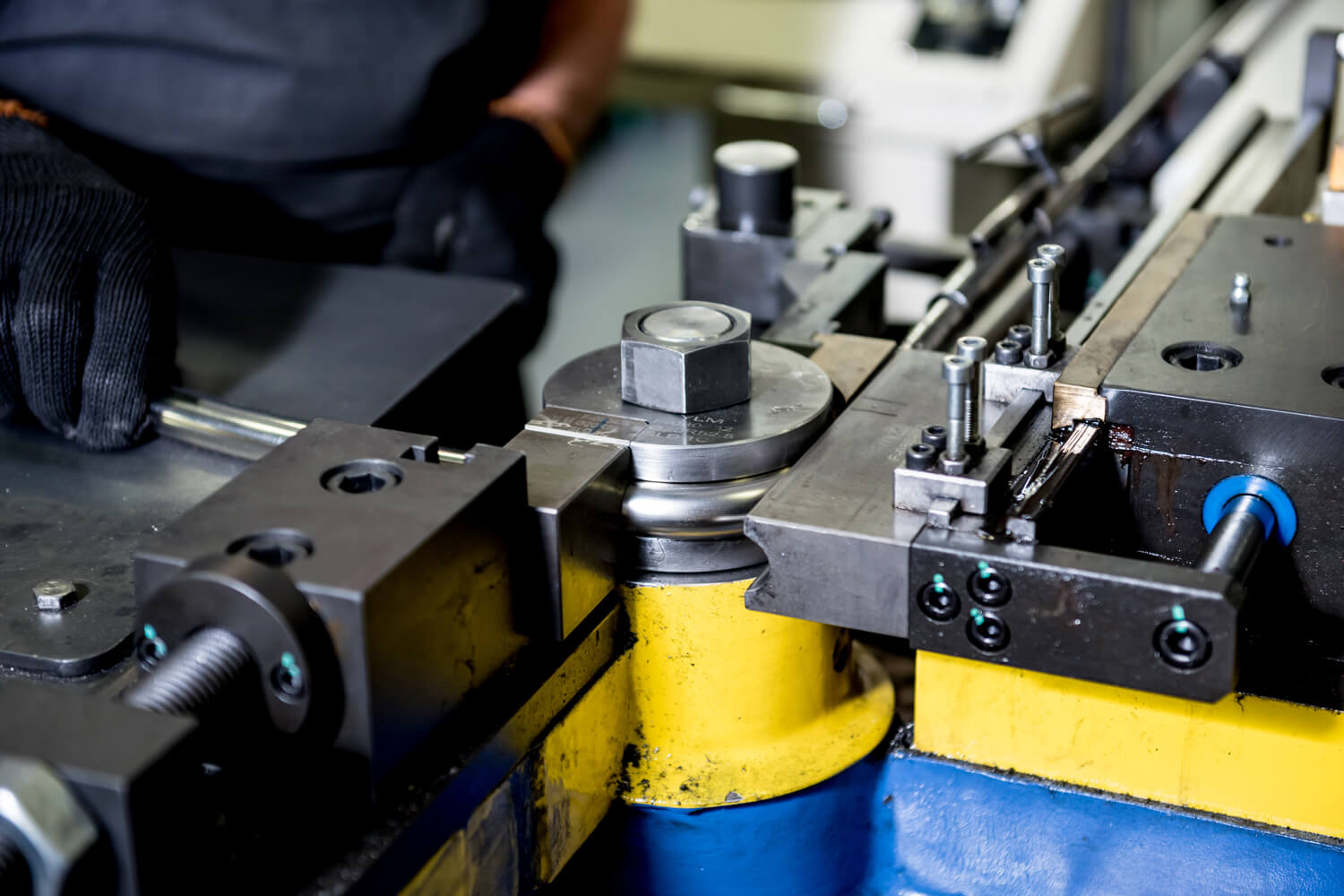
A mandrel is a hardened plug — plug mandrel, single ball, multi-ball or segmented mandrel — positioned inside the tube at the point of bend. The tube is clamped into a rotating bend die. A pressure die follows the outside of the bend, and a wiper die supports the inside radius. As the die rotates, the tube is drawn around the radius while the mandrel holds the bore open from the inside.
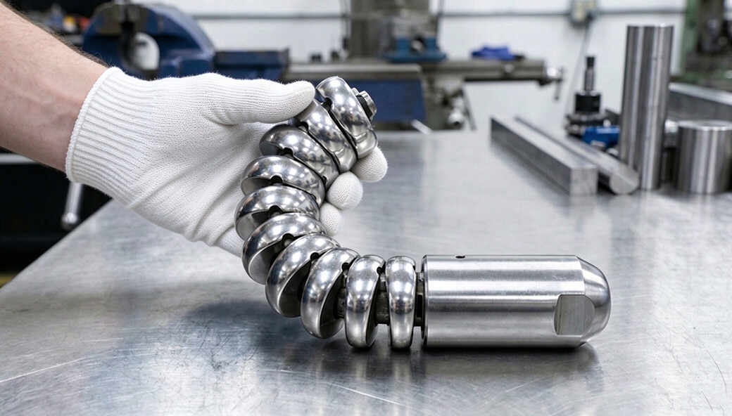
Three things follow from that internal support:
1. The inside radius cannot collapse inward, so ovality stays low.
2. The outside wall still stretches, but the strain spreads over a longer arc.
3. Wrinkles on the inside radius are held back by the wiper die rather than by wall thickness alone.
Mandrel bending is a rotary draw process. In favorable wall conditions it reaches centerline radii down to about 1× tube diameter (1D); routine production at 1.5D to 3D is common. It also handles compound bends — several bends in different planes — in one setup, which is what a header or a downpipe needs.
How Compression Bending Works
Compression bending — also called ram bending or press bending, depending on the shop — pushes a curved forming die against a tube that is clamped at both ends. Nothing supports the inside of the tube. The material redistributes to match the die: the outside wall thins, the inside wall thickens and tends to wrinkle, and the cross-section flattens.
Tooling is simple. One form die per bend geometry, no mandrel, no pressure die set, no wiper die. Setup is fast and the machine hour is cheaper.
That makes it the right tool for large-radius work: single-plane sweeps above roughly 3D, and parts where the bend is structural or cosmetic instead of a sealing surface or a flow path.
Side-by-Side Comparison
| Parameter | Mandrel bending | Compression bending |
|---|---|---|
| Internal support | Hardened mandrel at the bend point | None |
| Typical centerline radius | Typically around 1.0D; can be smaller if wall thickness conditions are favorable. | 3D and above |
| Ovality at the bend | Low, held to drawing callout | Visible flattening; worsens as R/D drops |
| Wall thinning, outside radius | Controlled and distributed | Higher and less predictable |
| Wrinkling, inside radius | Suppressed by wiper die | Common on thin wall |
| Bend-to-bend repeatability | High; CNC axes position each bend | Lower; springback varies with each part |
| Tooling per bend geometry | Bend die, clamp die, pressure die, wiper die, mandrel | One form die |
| Setup and changeover cost time | Longer | Short |
| Cycle time per bend | Slower | Faster on long sweeps |
| Compound / multi-plane bends | Yes, one setup | Limited |
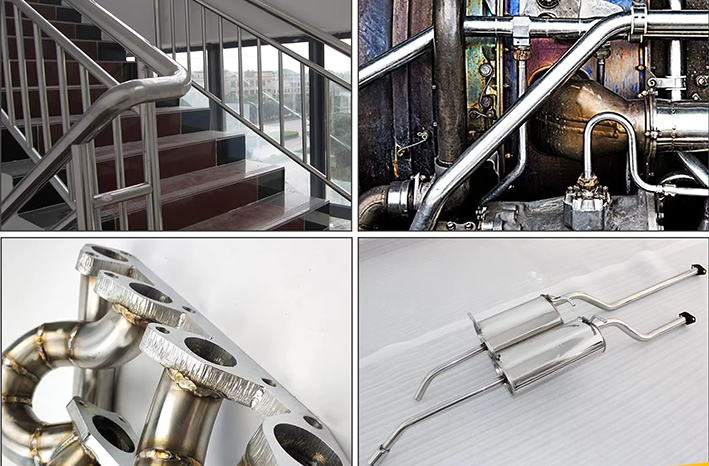
| Typical exhaust use | Headers, downpipes, cat-back, tight engine-bay routing, etc | Long frame-side sweeps, non-critical runs |
The ovality gap is the one that decides most exhaust jobs. A mandrel bend can be held to a few percent of nominal OD; a compression bend on the same tube typically flattens several times more, and the amount moves with wall tolerance from lot to lot.
Where each pays off:
· Mandrel bending wins when the drawing carries an ovality or wall callout, the joint seals against the outside diameter, the radius is under 2.5D, or the system ships as a kit that must bolt up in the field.
· Compression bending wins when the sweep is 3D or larger, the bend carries no dimensional callout beyond fit, the part does not seal at the bend, and volume is too low to absorb new tooling.
One cost point that gets missed: tooling is quoted per bend geometry, not per part. But a tighter mandrel bend often removes two miter cuts and one weld. Each weld you take out removes a leak path, a heat-affected zone, and the labour to fit and dress it.
PINOMETAL's Mandrel Bending Capability
We run mandrel bending for custom exhaust and industrial parts, built to your drawing. What that means in practice:
Bend radius: Centerline radius down to about 1.0 × OD in regular work; tighter figures on thick-wall tube with special tooling are possible — confirm against your print
Materials: Carbon steel, aluminized steel, stainless steel, aluminum, titanium and copper, plus selected nickel alloys
Geometry: Multiple bends in different planes, positioned and rotated in one setup; a straight leg long enough to clamp is required before and after each bend
Quotation: Returned with tooling status — existing die set or new tooling — and estimated lead time
What you gain from the mandrel, in exhaust terms:
1. Roundness where it seals. A band clamp, slip joint or V-band seats on the outside diameter. An oval end leaks, because the clamp pulls it further out of round instead of closing the gap.
2. Tighter routing, fewer welds. 1.0D to 1.5D bends clear obstacles in an engine bay or chassis rail that a 3D sweep cannot, and every removed weld is one less place to crack.
3. Repeatable fit for kits. CNC bend positioning puts every segment in the same place, so hanger brackets and flange faces line up without forcing during field assembly.
4. Material range under one roof. From stainless steel and aluminized steel to aluminum and nickel alloys, material selection and tooling are tailored to application needs, formability, and corrosion resistance to maintain tube geometry.
Common Tube Bending Problems and Solutions: Insights from PINO Engineers
Most scrap on bent tube traces back to a handful of defects. Our engineers will investigate these issues and make the necessary adjustments.
| Defect | Likely cause | What we change first |
|---|---|---|
| Ovality or flattening | No inner support, or mandrel nose set too far back | Advance the mandrel nose to the tangent point; add ball segments; reassess R/D against the wall factor (D/t) |
| Wrinkles on the inside radius | Pressure die too slack, wiper die misaligned or worn, too much clearance between mandrel and bore | Raise pressure die force, reset the wiper die at the tangent point, reduce mandrel-to-bore clearance |
| Wall thinning above the drawing limit | Radius too tight for the wall, mandrel set too deep, no boost feeding material into the bend | Increase the centerline radius if the layout allows it, reset mandrel depth, apply boost pressure |
| Scoring or mandrel lines inside the tube | Dry mandrel, worn ball segments, wrong clearance | Increase and monitor lubrication, re-machine or replace the balls, re-set nose position |
| Bend angle drifting out of tolerance | Springback change between material lots, compensation value out of date | Measure one part, update the overbend value, verify consecutive pieces before releasing the run |
| Tube slipping in the clamp die | Straight leg too short, low clamp force, worn clamping surface | Confirm minimum leg length at quoting stage, raise force, re-serrate or replace the clamp |
| Coating cracking on aluminized steel | High surface strain on the outer radius | Ease the radius where the layout permits, review bend direction and coating side, agree the acceptable level with you before release |
| Ends out of round after cutting | Cut placed too near the bend | Move the cut away from the tangent point, or state a roundness requirement at the cut end on the drawing |
Please send the STEP file along with the drawing. Bend sequence and tool clearance are much cheaper to fix on screen than after tooling is cut.
FAQ
- Is mandrel bending always the better choice for exhaust parts?
- No. Above roughly 3D, with no ovality callout and no sealing surface at the bend, compression bending does the job for less money and often faster. Mandrel bending earns its cost where roundness, wall thickness or repeatability actually affect assembly or service life.
- What minimum wall thickness should I specify after bending?
- State it on the drawing. The outside radius always stretches, so the finished wall there is thinner than the tube you started with. Give the minimum acceptable figure at the bend, and the right starting wall and tooling can be selected against it instead of guessed.
- Do I pay for tooling on every new part?
- Tooling is per bend geometry, not per part. If the combination of OD, wall and radius already exists in our tool room, there is no tooling charge. The quote always states which applies.
- Which materials do you mandrel bend?
- Carbon steel, aluminized steel, stainless steel, aluminum, titanium and copper, plus selected nickel alloys. Give the exact grade rather than "steel" — springback, mandrel clearance and lubrication all depend on it.
Send Your Drawing for a Bend Review
Send outside diameter, wall thickness, material grade, centerline radius per bend, bend angle, developed length, end treatment and estimated annual volume — ideally STEP or DXF with the drawing — to Brian@cnpinometal.com. The quote comes back with tooling status and estimated lead time.